Selecting the appropriate scale for an architectural drawing is one of the most fundamental decisions in technical documentation. The scale you choose determines how much detail can be shown, whether the drawing fits on standard paper sizes, and whether your audience can interpret the information clearly. Get it wrong, and you risk cluttered drawings, missing critical dimensions, or non-compliance with planning requirements.
At Docuex, we work with architects, surveyors and property professionals to convert legacy paper drawings to CAD formats every day. Through our paper-to-CAD conversion service, we see firsthand how scale choices affect drawing legibility and usability. In this guide, we'll explain the principles behind choosing the right architectural scale for different drawing types.
Understanding Architectural Scale Notation
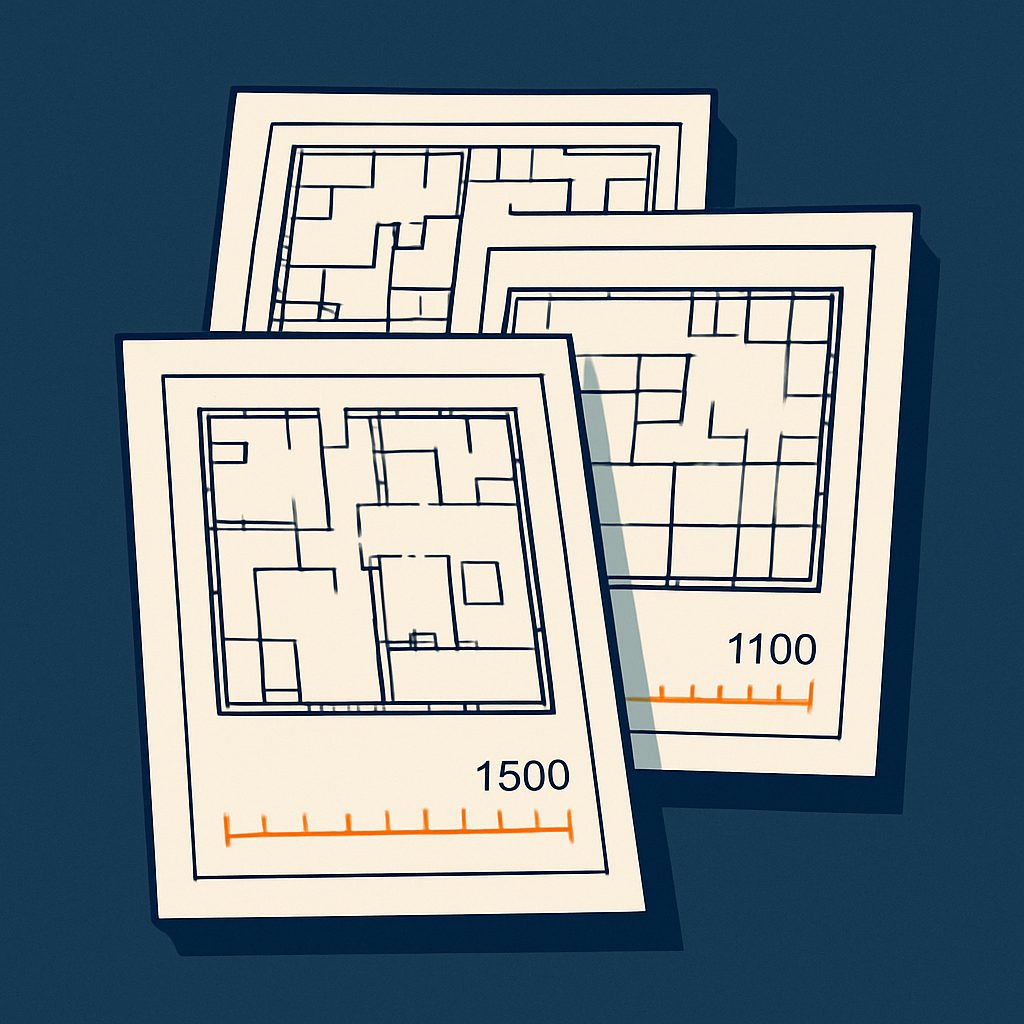
Architectural scales are expressed as ratios, such as 1:50 or 1:100. This notation means that one unit on the drawing represents a specific number of those same units in reality. For example, at 1:50 scale, 1 millimetre on your drawing represents 50 millimetres (or 5 centimetres) in the actual building.
The larger the second number in the ratio, the smaller the scale and the less detail you can practically show. A 1:200 drawing covers more area but shows less detail than a 1:50 drawing of the same building. Understanding this relationship is essential when planning your drawing set.
Common architectural scales in the UK include:
- 1:50, detailed floor plans, sections, elevations
- 1:100, general arrangement drawings, planning applications
- 1:200, site plans, large buildings, overview drawings
- 1:20 or 1:10, construction details, joinery, critical junctions
- 1:500 or 1:1250, site location plans, context drawings
Scale Selection by Drawing Type
Floor Plans and General Arrangements
For most residential and small commercial projects, 1:50 is the standard scale for detailed floor plans. At this scale, you can clearly show room dimensions, door swings, window positions, wall thicknesses and furniture layouts. Text annotations remain legible, and dimensions are easy to read without crowding the drawing.
When dealing with larger buildings or when you need to fit multiple floors on a single sheet, 1:100 becomes more practical. This scale is widely used for planning applications and provides sufficient detail for most regulatory purposes while keeping sheet sizes manageable. Our digital floor plans service typically delivers drawings at 1:50 or 1:100 depending on building size and client requirements.
Sections and Elevations
Building sections and elevations typically use the same scale as the corresponding floor plans to maintain consistency across the drawing set. For detailed sections showing construction build-ups, floor-to-ceiling heights and structural elements, 1:50 works well. For longer elevations or sections through larger buildings, 1:100 may be necessary to fit the drawing on A1 or A0 sheets.
When producing 3D visualisations from technical drawings, maintaining consistent scales across sections and elevations ensures accurate spatial representation.
Site Plans
Site plans usually require smaller scales to show the building in context with its surroundings, access routes, boundaries and landscaping. The 1:200 scale is common for site layouts showing immediate context, while 1:500 works for larger sites or masterplanning exercises.
For statutory site location plans submitted with planning applications, Ordnance Survey base plans at 1:1250 or 1:2500 are standard in the UK. These scales provide sufficient context without overwhelming detail.
Construction Details
Technical details require larger scales to show construction junctions, fixings and material interfaces clearly. Scales of 1:20, 1:10 or even 1:5 are common for details such as window heads and sills, eaves, parapets, stair construction and wall-to-floor junctions. At these scales, individual components become distinguishable and dimensions can be precisely specified.
Practical Considerations When Choosing Scale
Paper Size and Sheet Organisation
Your chosen scale must allow the drawing to fit appropriately on standard paper sizes. In the UK, architectural drawings typically use A0 (841 × 1189 mm), A1 (594 × 841 mm) or A2 (420 × 594 mm) sheets. The relationship between scale, building size and paper size is critical, our paper sizes reference guide provides dimensions for all standard formats.
A useful rule: leave adequate margins (typically 20-30 mm) and space for title blocks, legends and notes. If your drawing fills every millimetre of the sheet, consider using a smaller scale or splitting the information across multiple drawings.
Level of Detail Required
The drawing's purpose dictates the detail level needed. Early design presentations may use 1:100 or 1:200 to communicate spatial concepts without construction specifics. Building regulations submissions require sufficient detail to demonstrate compliance, typically 1:50 for plans and sections. Tender documentation needs precise information for pricing, often combining 1:50 general arrangements with 1:20 or 1:10 details.
When we undertake large format scanning of existing drawings, we often find that older drawings used scales appropriate to hand-drafting limitations. Digital workflows offer more flexibility, but the fundamental principles remain unchanged.
Consistency Across Drawing Sets
Maintain consistent scales wherever possible within a drawing set. If your ground floor plan is at 1:50, keep other floors at the same scale. This allows direct visual comparison and reduces errors when cross-referencing between sheets. When scale changes are necessary, clearly indicate this in title blocks and consider using different sheet series (e.g. 'D' prefix for detail sheets at larger scales).
Using Scale Calculators and Conversion Tools
Converting between scales, calculating actual dimensions from scaled drawings, or determining appropriate plot sizes requires mathematical precision. Our scale calculator tool simplifies these calculations, allowing you to input a scale ratio and physical measurement to find the real-world dimension, or vice versa.
This becomes particularly valuable when working with mixed-scale drawings or when you need to extract dimensions from scanned paper drawings that may have been copied or reproduced at non-standard sizes. Always verify the accuracy of older drawings by checking known dimensions against scale measurements.
Common Scale Selection Mistakes
Several pitfalls affect both new practitioners and experienced professionals working under time pressure:
- Overcomplicating simple projects, small residential extensions don't need 1:20 plans; 1:50 provides adequate detail without excessive drafting time
- Inconsistent scales within drawing types, switching between 1:50 and 1:100 for different floor levels creates confusion
- Ignoring text legibility, at 1:200, standard annotation text sizes become difficult to read when printed
- Failing to consider reproduction, drawings that look clear on screen may lose detail when printed or photocopied at reduced sizes
- Not matching regulatory expectations, local planning authorities often specify required scales for different submission drawing types
Need Drawings Converted at the Right Scale?
Our team produces editable CAD files matched to your standards and sheet sizes.
Get a Free QuoteScale Selection in a Digital Workflow
Modern CAD software allows you to draw at full size (1:1) and apply scale only when plotting or exporting. This approach offers flexibility, you can generate multiple views at different scales from the same model, but you must still consider scale when setting up viewports and sheet layouts.
Line weights, text heights and hatch patterns should be configured to appear correctly at the intended plot scale. A dimension text height of 2.5 mm when printed requires different model space text heights depending on whether the viewport is set to 1:50 or 1:100.
Making the Right Choice for Your Project
Choosing the appropriate architectural scale balances technical requirements, regulatory expectations and practical constraints. Start by identifying the drawing's purpose and audience, then consider the level of detail required and the physical size of what you're documenting. Check whether regulatory submissions specify required scales, and ensure your choice allows the drawing to fit appropriately on standard sheet sizes with adequate space for annotations.
When in doubt, following established conventions serves you well: 1:50 for detailed floor plans and sections, 1:100 for general arrangements and smaller-scale overview drawings, and 1:20 or larger for construction details. Maintain consistency within your drawing set, and always clearly indicate the scale in title blocks and when scales change between drawings.
At Docuex, we understand how scale choices affect drawing clarity and usability. Whether you're converting legacy drawings to CAD, digitising large format paper documents, or need assistance with technical drawing production, our team brings practical experience to every project. Get in touch for a quote and we'll discuss how we can support your documentation requirements with our 48-72 hour turnaround service.